CD-changing Lego® robot
Update 20050628: you may also be interested in my
system for pausing the
music when the phone is in use, which also announces
callers' names via voice synthesis.
LEGO® is a trademark of the LEGO® Group of
companies which does not sponsor, authorize or endorse this
site. The LEGO® Company have a pretty reasonable policy for
the use of their trademarks on non-Lego® webpages, so it's
only fair to go along with it. Hence the ® after every
mention of the word "Lego®".
 I recently bought a Squeezebox
from Slim Devices,
which is a way cool WiFi device for listening to your music
collection. I was then faced with the task of ripping c300 CDs,
and of course instead of just doing a handful every evening and
eventually getting through it, decided to build a robot out of
the Lego®
Mindstorms™ set which my wife and I received as a
wedding present. This is the result.
I recently bought a Squeezebox
from Slim Devices,
which is a way cool WiFi device for listening to your music
collection. I was then faced with the task of ripping c300 CDs,
and of course instead of just doing a handful every evening and
eventually getting through it, decided to build a robot out of
the Lego®
Mindstorms™ set which my wife and I received as a
wedding present. This is the result.
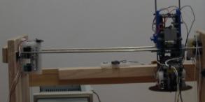
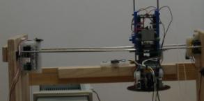
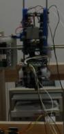
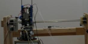
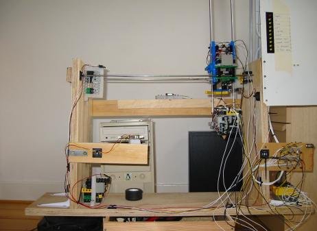
Not all of it is built of Lego® components: the frame is 18mm
plywood (left over from something or other), and the two sets of
rails are 4mm stainless steel rods. There's also a good number
of pieces cut from plastic chopping board, and some mahogony for
the part which actually picks up the CDs. But all the
interesting stuff is done with Lego® parts: the carriage which moves from
side to side, and the head which moves up and down. The RCX
brick controls it all, too, with a bit of help from an input
multiplexer. I didn't have to mutilate any Lego® bricks, with the
exception of buying some extra connection cables (from Bricklink) and chopping
them in half to make connections to/from my circuits and
switches.
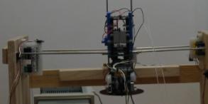
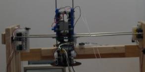
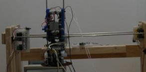
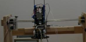
The robot has two movement axes --- left/right and up/down
--- and a third motor controls the grip/release of the CDs. The
whole physical design is very similar to a CD-changing
robot created by Matthias Wandel, but with a few differences
here and there. No point reinventing the wheel, after all.
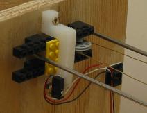
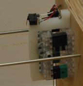
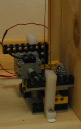
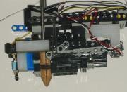
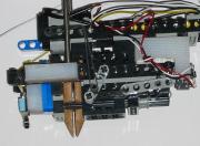
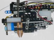
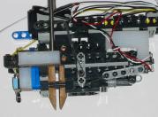
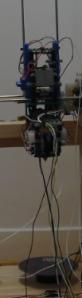
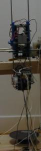
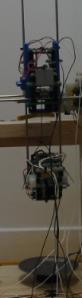
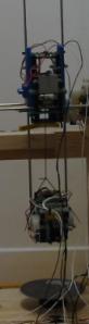
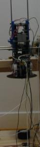
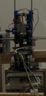
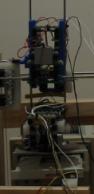
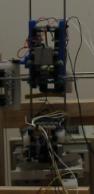
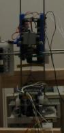
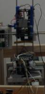
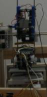
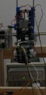
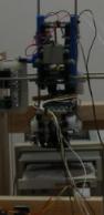
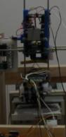
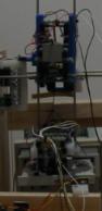
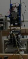
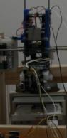
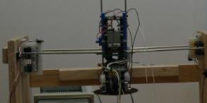
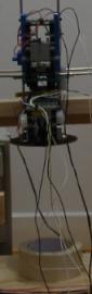
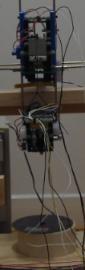
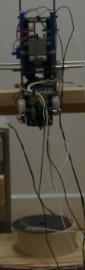
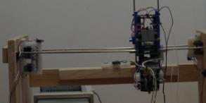
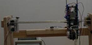
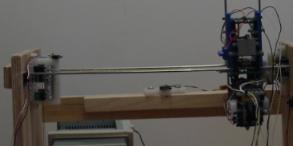
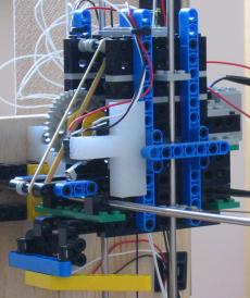
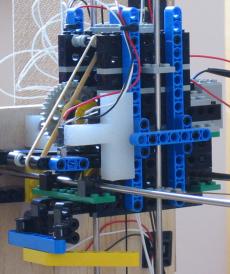
Left/right cable loop
The left/right movement is effected by a length of brass picture
wire, tied to one side of the carriage, threaded round a
horizontal pulley (left picture), passing clean back through the
carriage, round a vertical pulley (one of pulleys in right
picture), down to a drive wheel (bottom picture), back up to the
other, independently turning, vertical pulley (other pulley in
right picture), then finally tied onto the other side of the
carriage.
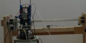
These pictures are taken from the other direction compared to
the main picture at the top of the page, to get a clearer view
of some of the parts.
There's enough tension on the picture wire that the rubber
wheel grips it and pulls the carriage left and right when it
turns, and the same limit-switch arrangement as for the other
two degrees of freedom (see below) stops the carriage trying to
go through the ends of the frame. Four jigsawed bits of
chopping board hold the pulleys and drive wheel to the
frame.
In common with all the other parts of the robot, it doesn't
move very quickly. It takes about one minute to completely
travel from one end of the rails to the other.
Up/down winch mechanism
The head is moved up by a winch which is part of the
carriage. It is moved down by gravity. It moves (roughly)
straight up and down, rather than swinging around randomly,
because of two guiding rods --- a better picture is in the
section on the CD-gripping fingers below. There are limit
switches at the very top and bottom of its travel. The one at
the top is simple enough, just a microswitch pressed by the head
when it reaches the top. The bottom limit was a bit trickier
because "the bottom" is at different heights depending on what
it's landing on at the time. The mechanism I used detects when
the weight of the head is no longer being supported by the
string, and is instead being supported by whatever it has landed
on.
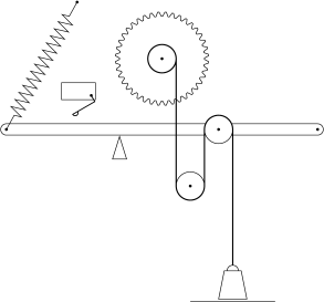
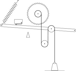
This is done by threading the winch string round two pulleys,
one fixed on the carriage, and one on a pivoted arm. The
pivoted arm is therefore pulled down by the string, and rests on
a support (a wedge in the diagrams below). There is a spring
(elastic band in real life) trying to pull the pivoted arm back
up, but the weight of the head is such that the weight wins.
But when the head lands on something, the spring wins as
slightly more string is paid out, and the pivoted arm rises, and
presses the "head is all the way down" limit switch:
| Just before head has landed on something
| After head has landed on something and a
small amount of extra string paid out
|
|---|
| 
|
| 
|
The yellow piece at the bottom of the carriage presses a
microswitch as the carriage moves through the centre of its
left/right travel. This needs to be detected because the
processed CDs are deposited in the centre of the robot's
frame.
CD-gripping fingers
The head, winched up and down by the mechanism above, lands
on a CD and needs to be able to pick it up. In fact it needs to
land on top of a pile of CDs, and pick up just the top one.
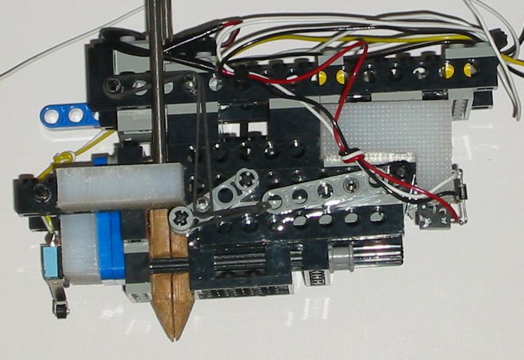
One finger (the left one in the pictures) stays still. The
other one slides left and right by means of a rack (on the
sliding carriage) and pinion (on the same axle as the grey arm
with two elastic bands attached). The pinion-arm is pulled by a
motorised arm via an elastic band and a rigid link. This is so
that when the fingers hit the sides of the CD's hole, the
motorised arm can continue to turn, so the fingers are pulled
against the sides of the hole by the tension in the elastic
band. The other elastic band is to pull the fingers back
together when the arm moves back. Playing around with the
different lengths of the arms and the elastic bands took a while
to get right but it was very reliable by the time I'd
finished.
The arm hits a microswitch at the limit of its travel thereby
turning off the current to the motor and simultaneously
signalling the RCX that the limit has been hit. See "limit
switches" section below for details on this.
The microswitch at the left of the head is pressed when the
head has landed on a CD or is holding one in mid-air. This
allows the RCX to detect if the CD has fallen off when it's not
supposed to. There is a third microswitch on the other side of
the head, which is the limit switch for when the motorised arms
are at their other (fingers closed) limit.
The shape of the fingers (hand-carved out of some scrap
mahogony I had left over from a door-saddle) is such that the
conical section allows the head to centre itself on the CDs as
it lands. The very short cylindrical section is then just large
enough to grip the hole of the top CD on a pile but not the next
one down. I stole this idea from Matthias
Wandel's machine but initially tried to make the shape by
turning some chopping-board. This failed miserably and the
hand-carving turned out to be a lot easier than I thought. The
bits of wood are fixed to the Lego® bricks by a 3mm screw which fits
through a hole in a beam, and happens to countersink very neatly
into the hole.
Two 4mm stainless steel rods (from Mail Order Metals)
are attached to two bits of chopping board, using what I think
is called "interference fit", i.e., jammed into 4mm holes. The
chopping board is fixed to the Lego® bricks by screws, same as the
wooden fingers. These are the guide rods to keep it moving
straight up and down.
In operation, but with no CD in place so you can see what's
going on:
(The fingers don't spread this far when actually picking up a
CD; the tension in the elastic band translates to force applied
by the fingers on the inside of the CD hole as mentioned
above.)
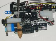
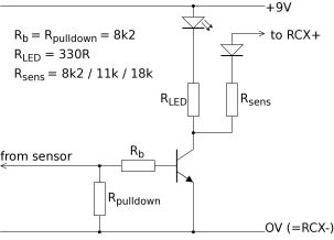
Switch inputs and LED panel
The RCX only has three inputs, but they are analog, connected
internally to a 10-bit (I think) ADC, with a 10k pull-up to the
full-scale voltage (5V I think). So we can, rather perversely,
build an external DAC to convert from a set of switch readings
into a voltage, present this voltage to the RCX's input, then
re-map the ADC reading in software inside the RCX to the switch
values. This idea I stole from here,
but tweaked the resistor values a bit to try to get better
separation between the eight points. And I used transistors as
well to be able to light up the LEDs at the same time.
The stripboard ended up looking a bit of a kludge but worked
fine. (Once I realised that I needed some diodes. Doh. And I
then realised that hardware is a lot more difficult to edit than
software.) It's three copies of the same circuit, and each
circuit is three almost-copies (differing only in one resistor
value) of the same element. The three almost-copies, one each
with Rsens of 8k2, 11k and 18k, have their "RCX+"
points tied together, and fed to one ADC input of the RCX. The
circuit diagram shows one element, so there are nine
almost-copies of this in the real thing.
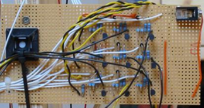
The three yellow/black twisted pairs go to the RCX's input
pads, and provide information on three switches each; nine in
total. The individual input wires (mostly black; one or two are
yellow) come from the various microswitches scattered around the
robot.
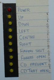
The bundle of white wires goes off to the LED display panel.
This has a red "power" LED and nine yellow sensor LEDs. The
numbers next to each label give the input number (1, 2 or 3) and
the bit value (1, 2 or 4) corresponding to that sensor. The
bit assignments are in a thoroughly random order.
There is a long and proud tradition of flashing lights being
a vital part of any piece of computer equipment. See "blinkenlights"
poem:
| ACHTUNG! ALLES LOOKENSPEEPERS! |
| Das computermachine ist nicht fuer gefingerpoken
und mittengrabben. Ist easy schnappen der springenwerk,
blowenfusen und poppencorken mit spitzensparken. Ist nicht fuer
gewerken bei das dumpkopfen. Das rubbernecken sichtseeren keepen
das cotten-pickenen hans in das pockets muss; relaxen und
watchen das blinkenlichten. |
Limit switches
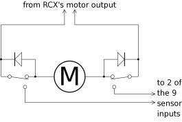
When, say, the carriage has moved as far left as it can, it
hits a microswitch. This cuts off the current to the motor, but
only in that direction --- if the current reverses, the diode
allows current to pass so the carriage is able to move
rightwards. When the microswitch is pressed, it also feeds the
9V from the motor output into one of the "from sensor" points in
the input circuit, allowing the RCX to detect that this limit
condition has been reached. Then I just had to make sure that
the motor connector was on the right way round, so that the
limit switches switched off in the right direction. Only two
possible ways round, so quick and easy. The "up", "down",
"left", "right", "fingers shut" and "fingers open" inputs are
all of this type.
Other switches
The "centre", "CD present" and "CD tray open" sensor inputs are
each just a microswitch which switches +9V to the relevant
transistor-circuit input when activated. This doesn't get
a diagram.
Software
The development environment supplied by Lego® is for
Windows systems, and is rather limited. Luckily, the
microprocessor inside the RCX brick is a Hitachi h8300, and the
GNU compiler collection from
the FSF can output h8300 code.
Some brave souls have written brickOS, an entire
replacement firmware for the RCX. In combination with emacs,
this gives you a powerful development system on a GNU/Linux
system, using entirely free
software. The program I wrote to control the robot didn't
make full use of the multithreading capabilities of brickOS ---
it was essentially a state machine which knew what it was
expecting to see next at all times, and changed state as the
various switch combinations appeared. Entering the next state
turned on/off the required motors to make the next thing happen.
If anything happened which it wasn't expecting, it panicked,
turning all motors off and flashing diagnostics on the display.
It also talked to the PC via the infra-red link to tell it when
to open and close its CD tray. Getting the cross-compiler and
brickOS up and running was a bit fiddly but not too difficult.
Writing the RCX program and the Perl script to control the PC's
side of things was fairly straightforward.
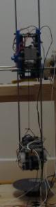
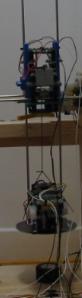
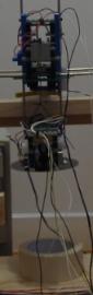
In operation
Apologies for the dark exposures on these pictures. I didn't
want to burn through too many camera batteries flashing every single
one. I tried to compensate by changing the exposure but stuffed
it up and got the adjustment the wrong way round, thus making
things worse. The pictures are good enough for me to not want
to set the whole photography arrangement up again, though.
Sorry.
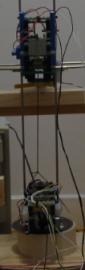
Here there is only one CD but it worked with a pile of CDs
balanced on top of the wheel. The head descends towards a new
CD:
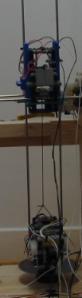
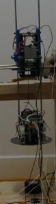
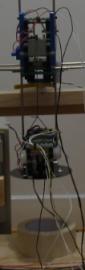
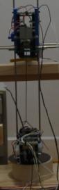
It lands on the CD, spreads the fingers to grip the CD's
central hole, and then ascends with the CD:
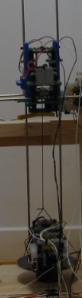
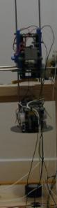
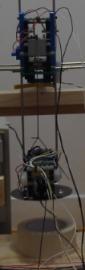
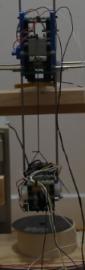
With the CD, it moves leftwards towards the computer:
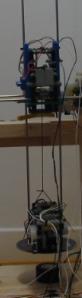
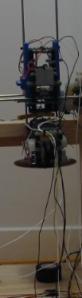
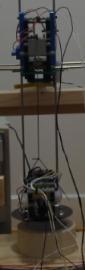
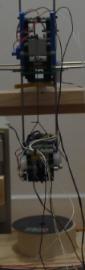
It signals the computer (via infra-red), requesting it to
open its CD-tray. Then descends with the CD and places it in
the waiting tray:
It closes its fingers, releasing the CD, and ascends
CD-less:
It signals the PC to close the tray and rip the CD:
When the PC has finished, it ejects the CD-tray, which
triggers the robot to start its descent onto the newly-ripped
CD:
When it lands, the robots spreads its fingers to grip the
ripped CD, then ascends with it:
It signals the PC to close its CD tray (just to get it out of
the way), then moves right, until it reaches the centre:
It stops here, then lowers the head to deposit the ripped CD
onto the "done" pile:
It closes its fingers, releasing the CD, and ascends again:
Finally, it completes the rightwards journey:
...ready to start the cycle again with the next CD.
Epilogue
Alas! I was thwarted in my dreams of completely unattended
runs of ripping fifty CDs at a time. It turned out that my old
CD drive and/or old Linux kernel did not handle scratched or
otherwise dodgy CDs very well. After a couple of retries, the
kernel would try to reset the entire CD-drive, which it didn't
like very much. It failed to respond to anything, and so the
kernel reset it again. This repeated every five seconds until I
noticed and rebooted the machine. A bit disappointing but I
didn't want to risk lashing the robot up to my good new PC just
in case something went wrong and it snapped the CD tray or
something. As it turned out, the most it did in a row without
hitting a bad CD was about seven or eight CDs, which was enough
to be satisfied that the robot worked reliably.
Contact
(Address as image to foil spam-harvesters, sorry.)